The Vth Generation of The INDUCTION DESIGN
KeiRiki series : Form Generation + Structural Aptimization
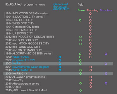
- KeiRiki-1 2003-2005
- : for frame structure
- KeiRiki-2 2006
- : for 3D-frame structure
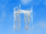
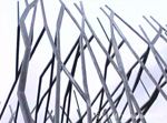
- :applied to ShinMinamata MON
- KeiRiki-3 2007-2011-
- : for shell structure
KeiRiki-1 / KeiRiki-2 : for frame structure
ALGODesign
INDUCTION / ALGORITHMIC : two names for the same process
In the final analysis, design is the act of solving problems by formulating answers that are backed up by the designer's intentions. The idea behind INDUCTION DESIGN is to make the process of problem solving more scientific (in the sense of verifiable).
The term "induction" is meant to suggest a process that results in a "better" solution, instead of selecting a single solution and declaring it to be the absolute, as has commonly been done up to now.
When a coil is brought near a magnet, an electric current is generated. Instead of being supplied directly, the current is generated by variations in the magnetic field.
A current generated in this way is called an induction current.
In design as well, instead of inscribing the final results directly on diagrams, it is possible to use programs that solve for specified conditions to "generate" designs that are "better".
This is the INDUCTION DESIGN method.
From another viewpoint, the same method can also be called ALGORITHMIC DESIGN , when we place more weight on clarifying the procedures that lead to the solution.
An algorithm is a procedure that specifies the initial steps to take in this situation, and what to do next.
In ALGORITHMIC DESIGN, a procedure is created by defining the value standards required in the design, assigning weights, and specifying the processing order, and then that procedure is used to carry out the design and obtain a better solution.
The term "procedure" as used here does not refer to a flow chart or other linear method. Back-and-forth convergence processing is required, making a computer program necessary.
These two names for the same process emphasize different aspects of its character.
INDUCTION DESIGN places the weight on the behavioral aspect of the design process, while ALGORITHMIC DESIGN places the weight on its formal aspect.
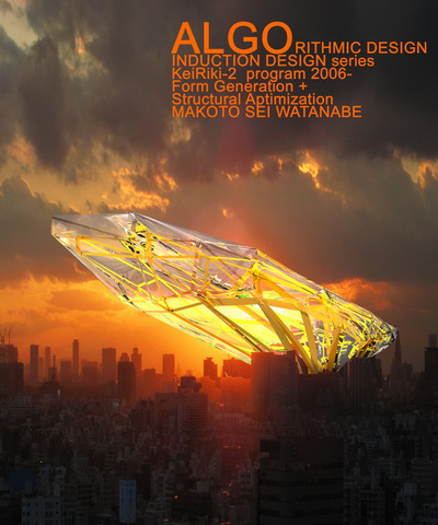
Form Generation + Structural Aptimization
KeiRiki-1 is the first open program in the INDUCTION DESIGN series.
It is one of the outgrowths of the WEB FRAME program.
WEB FRAME, which corresponds to INDUCTION DESIGN-III, was a program for "form generation + selective evaluation".
It did not include structural mechanics.
Wing, another program in the series, attempted to achieve integration with structure, but remained unfinished.
Following up on that objective, KeiRiki-1 incorporates the processing required for structural mechanics.
(In order to clarify the results of this processing, the program does not include an evaluation process. The evaluation process is being developed separately, as INDUCTION DESIGN-IV Program of Flow.)
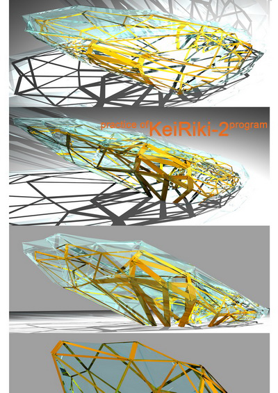
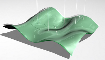
KeiRiki-2 is an advanced version of KeiRiki-1 program.
It can treat structure with surface (;such as glass, wall, etc.)
Wind load acting on the surface is automatically calculated.
Definitions of "conditions" and "aptimized (optimal)"1*
The purpose of this program is twofold:
1) to generate forms that solve given conditions,
and
2) to generate aptimized (optimal) structures to support the loads imposed on those forms.
Given conditions can vary from case to case.
They vary depending on what is being made, where it is made, and how it is made.
To make any progress at all, we need to start by deciding something, so this program defines the range and type of conditions as described below.
Of course it would be possible to select different conditions.
If you need to solve different conditions, you can always write a different program.
What is important is not the selected conditions (the possibilities are endless), but rather the proof that a program is capable of solving the selected conditions.
The meaning of "aptimized (optimal) structure" also needs to be defined.
This program judges "optimal" according to the standard of weight.
That is, aptimized (optimal) was defined to be "discovery of the structure for a generated form which, given a specified load and specified materials, has the lowest total material weight".
Other definitions of aptimized (optimal) are possible. One could judge by the number of structural members, the number of member types (fewer being better), the degree of sectional variation, and so forth.
If these are the conditions to be solved, then a program could be written to solve them.
Once again, the important thing is not what is chosen to be aptimized (optimal).
The goal is to prove the effectiveness of a program in solving the conditions for the selected standard of [o|a]ptimization.
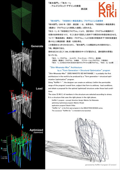
The KeiRiki-1 2) program integrates two processes.
One is a "form generation program" and the other an "aptimization (optimization)" program.
Using KeiRiki-1, the designer can create an arbitrary (within the permissible range of the program) overall form, subject that form to arbitrary load conditions, and obtain a proposal for the aptimized (optimal) structure under those load conditions.
The results are different for every iteration, depending on the parameters specified for each process in the program.
The shape and size of the continuous surface, the selection of parameters for the form generation process, the number of openings, and the selection of materials for the aptimization (optimization) process all affect the results.
In every case, the results emerge as solutions which solve the specified conditions, not simply as a number of different variations.
note 1*:
Optimal is a technical term in structural mechanics. However, in view of its meaning, the term itself seems less than "optimal". In structural mechanics, "optimal" refers to a solution which, given selected conditions, can be viewed as meeting the conditions to a higher degree than other solutions. In other words, it refers to a relative and approximate solution.
This seems rather inadequate in view of the usual meanings of both the English word "optimal" and the Japanese word saiteki (most appropriate), which is normally used to translate it.
Therefore the Japanese version of this text coins and concurrently uses the term koteki (very appropriate).
The English translation uses the notation "aptimized (optimal)" to refer to this combination, to suggest both the technical meaning and another meaning which might be described as "highly apt or appropriate".
It is possible to have any number of good things, but it seems difficult to call one of then "optimal" unless it is actually the best.
Of course technical terms are not required to mean what they mean in everyday speech. But honoring everyday usage is still a desirable goal.
(Needless to say, these observations about the term "optimal" do not imply any reservations regarding the concept of optimization, or the quality of methods used to achieve it.)
note 2:
The term "KeiRiki" is made up of two parts.
The first part, "kei" (also pronounced "katachi"), is the Japanese word for "form".
Here it refers to the generation of form.
The second part "riki" (also pronounced "chikara") is the Japanese word for "power". Here it refers to "kozo-rikigaku", or structural mechanics.
note 3:
-
Improved points from KeiRiki-1 to KeiRiki-2:
- Treating the structure with surface
- Keeping initial form in aptimizing (optimizing) process
- Being possible to change the form after aptimizing (optimizing) process
- Improved interface and some commands
Further explanation of KeiRiki-2 will be described later.
KeiRiki-1 :
Parts of the program : A+B
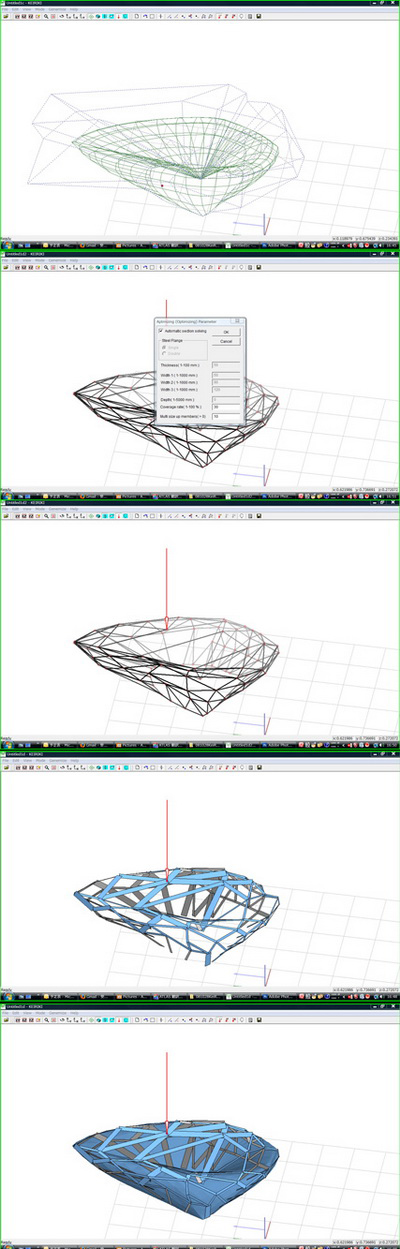
part A : Form/shape generating program
1 Specify the overall curved surface : Mode
: Select Mode:
First, specify the overall shape of the surface.
The shape here is a continuous curved surface.
Three basic types are selectable -- flat surface, arched curved surface, and arbitrary surface with the addition of torsion.
: Shape Edit Mode:
Arbitrary transformations can be applied to the selected basic surface, using intuitive operations.
: Edit - Add Hole:
Add holes to the surface.
The holes become reserved regions in the subsequent form generation process -- no form is generated within their ranges.
: Edit - Edit Hole:
These regions can be reshaped at a later time. (Reserved regions are not absolute. Under some conditions, forms may be generated within reserved regions.)
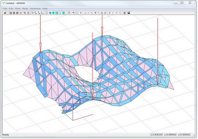
2 Generate the form : Gene-mize - Generate mode
Next, generate a net-like shape on the surface.
(This is processed in the next stage, and becomes the structural members.)
The entire shape does not appear all at once; it grows in certain directions.
This is because the shape generation procedure uses a branching, point-by-point generation algorithm.
This algorithm is intended to be similar to the growth mechanisms of biological organisms.
The conditions of this process are specified by the selected parameters.
(An automatic easy setting mode and a manual setting mode are provided.)
The overall scale (size) is also decided at this stage.
As related above, this form generation program does not incorporate any evaluation circuits.
It generates shapes exactly according to the input parameters.
Evaluation is left up to the designer.
(The Program of Flow with built-in evaluation functions is being developed separately.)
part B : Structural aptimization (opti- ) program
3 Specify the load : Load Edit mode
The "dead load" and "wind load" applied to the shape obtained from the generation program are set automatically.
Because this program envisages structures without skins, the wind load is limited to the load applied to the net-like structural members. The designer may additionally apply loads to arbitrary points.
This corresponds to design conditions such as locally supported floors, additional skins, and so forth.
(There is an easy mode which takes only vertical load into account, and a manual mode which allows loads to be applied in any direction.)
4 Perform structural aptimization (optimization)
: Gene-mize – Apti/Opti mize
The type of structural members to use is selected here.
Depending on the overall size, the designer selects either single or compound type, and selects from three member widths.
(Compound type refers to a parallel arrangement of two identical members separated by an interval which remains constant regardless of stress.)
(Here again there is an easy mode which automatically selects the appropriate members, and a manual selection mode.)
The program does its processing according to the conditions specified above.
The basic algorithm is to repeat the procedure "increase the size of members subjected to greater stress than other members" until a specified number of repetitions or an aperture ratio limit is reached. Then, proceeding in reverse, decrease the size of members as long as a stress limit is not exceeded (as long as the members are safe). Finally, delete all members which are not connected to any other members.
The structure obtained in this way is an "aptimized (optimized)" structure.
The entire sequence of processes is carried out automatically.
(Results vary depending on the algorithm, for example the order of increase and decrease, so in this case "aptimized (optimized)" does not refer to an absolute, unique solution.)
Judgment of the acceptability of structural members is based on Japanese law, according to the Design Standard for Steel Structures of the Architectural Institute of Japan.
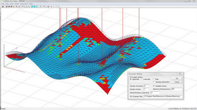
The program displays an overall shape every time it executes,
even when the structural conditions are not met.
Members which do not meet the conditions are displayed in red,
making it possible to adjust member size specifications for further repetitions of the optimization process.
Use of the program:
"KeiRiki-1w" may be downloaded from this site and used free of charge. However, the creation of derivative works, commercial use, and so on are prohibited without the express written consent of the author.
(Permission may be denied in some cases.)
When you release or publish the result ( ; design, research, thesis, program, etc.) achieved by using this program or referring to this program, it is necessary to describe clearly about it indicating the name of this program and the authors.
This program is intended for educational purposes only.
It is not intended for use in actual architectural design.
The author shall not be liable for any claim arising from use of the program (see the "Disclaimer" below).
Questions regarding use of program will not be answered.
Constructive suggestions and opinions will be accepted, but may not be answered.
"KeiRiki-1w" is an open version of "KeiRiki-1", which was actually used in the design of "Shin-Minamata-Mon". It shares almost all of the functionality of the original version.
For other information about the program, please refer to the README file.
KeiRiki program family:
"KeiRiki-1": The program used in the design of "Shin-Minamata-Mon"
"KeiRiki-1-w": The open version made available on this site.
The author: Makoto Sei Watanabe, Makoto Ohsaki, Takashi Chiba
DISCLAIMER:
"KEIRIKI-1W" (THE PROGRAM) IS PROVIDED "AS IS", WITHOUT WARRANTY OF ANY KIND, EXPRESS OR IMPLIED, INCLUDING BUT NOT LIMITED TO FITNESS FOR A PARTICULAR PURPOSE AND NONINFRINGEMENT. IN NO EVENT SHALL THE AUTHOR BE LIABLE FOR ANY CLAIM, DAMAGES OR OTHER LIABILITY ARISING FROM, OUT OF OR IN CONNECTION WITH THE PROGRAM OR THE USE OF THE PROGRAM.
"KEIRIKI-2" (THE PROGRAM) IS PROVIDED "AS IS", WITHOUT WARRANTY OF ANY KIND, EXPRESS OR IMPLIED, INCLUDING BUT NOT LIMITED TO FITNESS FOR A PARTICULAR PURPOSE AND NONINFRINGEMENT. IN NO EVENT SHALL THE AUTHOR BE LIABLE FOR ANY CLAIM, DAMAGES OR OTHER LIABILITY ARISING FROM, OUT OF OR IN CONNECTION WITH THE PROGRAM OR THE USE OF THE PROGRAM.
Download "KeiRiki-2"  :800KB
Download "KeiRiki-1w"  :900KB
Descriptions of parameters and algorithms: (about KeiRiki-1w)
General description
'KeiRiki-1w' generates a mesh-type optimal structure for a given curved surface or a plane under specified growing rule.
Outline of generating process
1. Specify the type of the surface.
2. Generate a mesh under specified condition.
3. Assign nodal loads.
4. Select a list of members.
5. Carry out structural optimization.
Technical terms
Shape : curved surface or a plane; arbitrary given under some restriction.
Node : a point located on the surface.
Member : a segment of a line between two nodes.
Branching : the state where two members grow from a node.
Evaded region : a region where no node or member can exist; arbitrary given.
Part A Shape Generating Program
1 Input variables
All the variables can be set by KeiRiki-1w.
| 1. | Iran Initial seed for random variables (arbitrary natural number). The shape can be controlled by modifying Iran. |
| 2. | Npmax Upper bound for for the number of nodes Np (less than 4000). Since branching is done simultaneously at all the front nodes, the generating process terminates if Np exceeds Npmax. Also Np might be reduced by the postprocess of deleting unnecessary members. |
| 3. | Nfp Number of initial front nodes at the lowest boundary. |
| 4. | Xfp Locations of the initial front nodes. Number of nodes is Nfp and 0< Xfp<1. |
| 5. | L0 Standard length of members (preferably between 0.1 and 0.2). |
| 6. | ΔL Ratio of standard deviation of member length to L0 (preferably about 0.2). |
| 7. | θ Standard value of branching angle (preferably between 20 and 30 degrees). |
| 8. | Δθ Ratio of standard deviation of branching angleθ (preferably about 0.2). |
| 9. | Lmin Minimum value of member length (preferably between 0.1 and 0.2). The member shorter than Lmin is to be removed and nodes connected by it are combined. |
| 10. | θmin Minimum value of branching angle (preferably between 0.1 and 0.2). If the angle is less than θmin, one of the branching members is to be removed and the nodes generated by the members are combined. |
| 11. | Stype Surface type |
| 12. | Rx, Ry Center of evading region |
| 13. | Rr Radius of evading region |
2 Algorithm
First generate the shape on the normalized plane (0<x<1, 0<y<3), and map it on the surface or cube.
| 1. | Assign Nfp front nodes on the lowest boundary. The coordinates are denoted by (Xi,Yi),(I=1,2,…,Nfp), where the two end-points of the lowest boundary are (0,0) and (1,0). | |
| 2. | Let the initial direction be θi=(0,1), (I=1,2,…,Nfp). | |
| 3. | Generate branches (k=1,2) at all the front nodes as follows: | |
| 1) | Generate uniform random number r between 0 and 1, and define the member length Lk by Lk=L0[1+ΔL](0.5-r)] |
|
| 2) | Generate uniform random number r, and define the member directionθk(k=1,2) by θ1=θi -(θ0/2)[1+Δθ](0.5-r)] θ2=θi +(θ0/2) [1+Δθ](0.5-r)] |
|
| 3) | Locate a new node by moving from node i in the direction of θk , and add a member to connect node I and the new node. | |
| 4) | If the member intersects with the boundary of the evaded region where no node or member can exist, add a new node at the intersection. | |
| 5) | If the member intersects with an existing member, connect the node i with one of the end node of the existing member that is farther than node i. Hence, the member is added without increasing the number of nodes. | |
| 6) | Let the new nodes be front nodes, where the generating directions are defined by the directions of the new members. | |
| 4. | Update the lists of members and nodes. | |
| 5. | Go to 3 if the number of nodes is less than Npmax. | |
| 6. | Carry out the following process until no short member of narrow branching angle exists. | |
| 1) | Combine the two end nodes of the member whose length is less than L0 *Lmin. | |
| 2) | Delete the shorter member of a branch whose angle is less than θ0*θmin. | |
| 3) | Remove the floating nodes. |
Part B Apti/Opti mizing Program
1 Input variables (opt.dat)
The variable that is NOT indicated by `INPUT FROM KeiRiki-1w' should be modified by directly editing `opt.dat.'
1. E, ν, ρ Elastic modulus, Poisson's ratio, Weight density (Default values for steel are given)
2. h Thickness of member; indicates the thickness of flange if Nplate =2. (INPUT FROM KeiRiki-1w)
3. σb Upper-bound stress (Increase (decrease) if the optimal members are too thin (thick); standard value of steel is given)
4. Sx, Sy, Sz Scale parameter for x- , y-, z-directions. (INPUT FROM KeiRiki-1w)
5. Ncs Number of member widths given in `dv.dat'. (INPUT FROM KeiRiki-1w)
6. Stype Type of surface (1: Bezier or twisted Bezier, 0: Cube; DO NOT MODIFY).
7. Nmax Number of maximum iterations (Decrease if computational time is too much.)
8. Dmax Maximum ratio of the occupied area to the total surface area (Decrease if computational time is too much.)
9. IC Level of correction after optimization (0: none, 1: low, 2:high; DO NOT MODIFY)
10. Is Scaling parameter (1: automatic, 0: manual) (INPUT FROM KeiRiki-1w)
11. Nplate Number of flanges (1: single, 2: double) . Disabled if Is=1. (INPUT FROM KeiRiki-1w)
12. Dplate Distance between flanges (1: single, 2: double) . Disabled if Is=1 or Nplate =1. (INPUT FROM KeiRiki-1w)
2 dv.dat
Set by KeiRiki-1w.
List of member widths Wi (i=1,2, …, Ncs) for ranks 1,2, …, Ncs.
Increase Wi (i=2, …, Ncs) if computation time for optimization is too large.
Increase (decrease) Wi (i=2, …, Ncs) if there exist too many members with largest (smallest) rank in the optimal solution.
DO NOT MODIFY W1.
3 Load.dat
Set by KeiRiki-1w.
1. Nload Number of loading sets.
2. Iload Set number.
3. Jmin, Jmax Lower and upper bounds of nodes to be loaded by this set.
4. Px, Py, Pz Load vector.
Numerical output data
1. At iterative steps of optimization: (result.dat)
Member number for which the rank of width is increased, Total structural volume, Maximum value of stress ratios σR among all the members, Ratio of the occupied area to the total surface area.
2. After optimization: (violate.dat)
Member number withσR>1, and the value of σR.
4 Apti/Opti mization algorithm (increasing process)
A heuristic optimization method called `greedy method' is used.
The minimum rank is initially assigned for the widths of all the members.
At each iterative step, the rank of the width of the member with maximum stress ratio among all the members are increased if it is not at the upper-bound level.
This way, an approximate optimal solution that minimizes structural volume for specified upper bound of stresses or strain energy can be obtained within moderately small computational time.
The algorithm is summarized as follows:
1. Assign the smallest rank for the widths of all the members.
2. Compute loads.
: Wind load
Apply 3.372 kN per m2 of member area in the y-direction, which is computer from the Japanese building code.
The half of the load for each member is applied at two nodes connected by the member.
The loads are applied at the only vertical plane for a cube; the loads are given at all the nodes for a Bezier surface.
: Self-weight
The self-weight of a member computed from the volume and weight density is applied in the vertical direction.
The half of the weight for each member is applied at two nodes connected by the member.
3. Solve the standard stiffness equation for static analysis to obtain the stress ratios of the members.
The allowable stress is defined along with the Japanese code for steel structures.
The stresses are computed at all the four corners of each member to find maximum absolute value of stress that is divided by the allowable stress to obtain the stress ratio.
Two load cases in positive and negative y-directions are considered for wind loads.
4. Let J denote the set of members that has a rank below the maximum value.
Increase the rank of the member with maximum stress ratio among all the members in the set J.
5. Terminate the process if the number of iterative steps exceeds Nmax or the ratio of the occupied area to the surface area reaches Dmax; otherwise go to Step 2.
5 Apti/Opti mization algorithm (decreasing process)
Iteratively remove a floating member, and a cantilever-type member if no additional load is applied at the end of the cantilever.
General Specifications
Units: `m' for length, `kN' for force.
The nodes at the ground level are automatically fixed as supports.
- Movie